Hand Tool Headlines
The Woodworking Blogs Aggregator
“Glory to God in the highest heaven, and on earth peace to those on whom his favor rests.” - Luke 2:14
Be sure to visit the Hand Tool Headlines section - scores of my favorite woodworking blogs in one place.
Woodworks by.John

Imitation is the Sincerest Form of Flattery
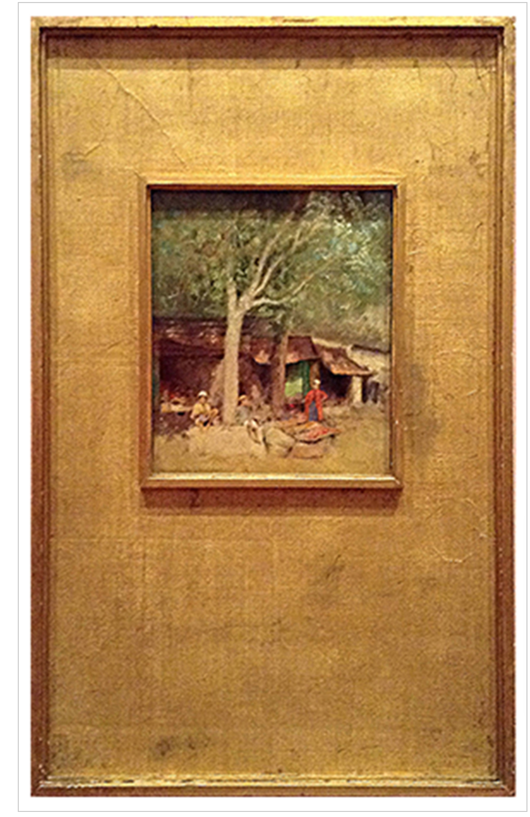
I’m betting that many of you have heard the phrase so that’s why I’m using it for this blog. It’s a phrase that has been attributed to many different people. This frame showed up on my Pinterest one day and it really appealed to me. It was originally from The Frame Blog which discussed Australian artists work from the late 1800’s. Those frames were made in Japan. The blog showed some of the construction details which consisted of the moldings assembled with miters and cross dowel construction. The framework was covered with paper or cloth. My wife recently completed a 10″x10″ figurative painting and I thought her painting would be a good fit for this style of frame. This work of her’s is going to her gallery, Meyer Vogl in Charleston, SC. It’s for their Ten Year Anniversary show the end of March.
The first part I made was the spandrel. That’s the piece that is inside of the frame; for tabernacle frames they are often curved or arched at the top. From the blog I learned that this frame had a lattice like arrangement of wood which was covered by material or paper. I chose to use 1/4″ MDF for that but still needed to figure a way to support the painting inside of the spandrel. Unfortunately I neglected to take a picture of that before cutting it open but milled some pieces of Basswood 13/16″ square which were glued, pin nailed and clamped to the back of the MDF. The reason for 13/16″ is so that I could pin nail from the backside with 1″ nails and not go through the front — that would not have been good!
 Completed spandler
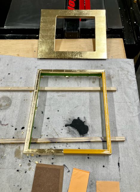
The exact opening in the grid on the back is 10″ x 10″ and was removed on the router table with a pattern cutting bit. However; the opening needs a rabbet for the painting to sit behind. I used 3/16″ spacers which were attached with double sided tape. The first step was cutting the opening with a pattern cutting bit on the router table. Next, a small roundover bit formed a radius. You can see the rabbet in the left picture after the 3/16″ spacers were removed. The picture on the right shows the completed spandrel sealed with 4-5 coats of Zinsser seal coat shellac. There was some debate in my mind about using the MDF for the spandrel since it can be affected by moisture. Since I had MDF in my shop and had success with a very large tabernacle frame commission decided to use it. In addition to multiple coats of sealing shellac the next step will be a yellow burnisher/sealer followed by slow set oil size, and finally imitation gold leaf.
Once the spandrel was made it was time to start creating the molding for the frame. I liked the small, unobtrusive molding on the original piece. I’m imitating that so started out with 3/4″ x 2 3/4″ Basswood. Simplicity was my goal so the top of it has a shallow profile created with a router bit used to make tray bottoms. Knowing it’s almost impossible to center it exactly the insides were marked so that the rabbet is on the same side of each piece. Before cutting the rabbet I took the time to sand a slight radius on the upper edges to prevent the gold leaf from cracking (left picture below). The rabbet was cut on the tablesaw with a rip blade. Marks were made with a marking gauge, the first cut was done flat at the top of the rabbet. Cutting off the remainder of it required careful set up with feather boards and my shop made push stick (right picture below). It took some careful set up and planning but the creating the molding was a success. I know I only need 4 pieces for a frame but cut some extra just in case.
 Profile in progress before creating the rabbet
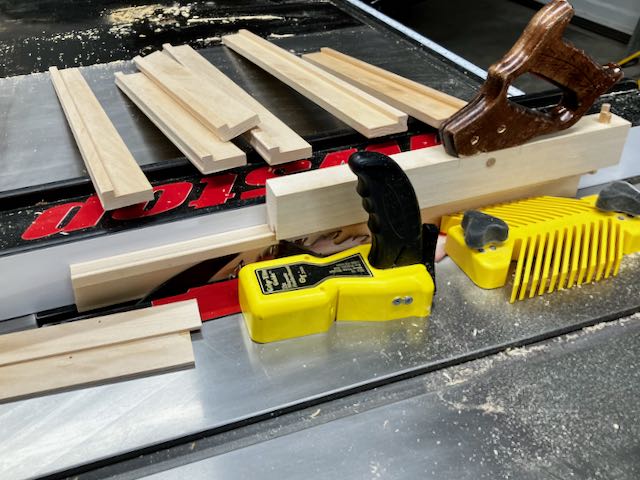 Rip blade for rabbeting
The frame was assembled in the usual way, after cutting the miters it was glued up and clamped with a band clamp overnight.
My usual procedure is to apply a coat of Zinsser seal coat shellac to the frame followed by Yellow burnisher sealer. I use slow set, oil based size and gilded the frame and the spandler at the same time. I wait at least 24 hours then burnish the imitation gold leaf with 4/0 Liberon oil free steel wool. The final finish on both of them is several coats of Platinum Blonde shellac applied with an airbrush. To mellow out the gloss of shellac, Liberon wax is applied with 2500 Mirlon abrasive pad. All that’s left is assembling the frame and spandrel.
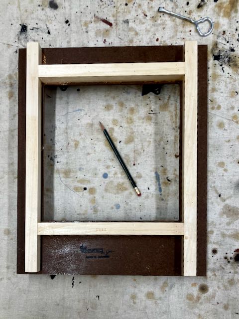
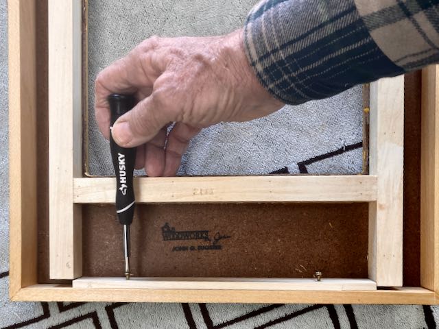
This was a bit of a challenge since there is a very limited amount of space to insert a fastener between the frame and the lattice work on the spandrel for attachment. That dilemma was solved by using a piece of Basswood that I had pre-drilled holes at a slight angle. After putting that piece in place the holes were marked with a pencil. A gimlet was used to create an angled starter hole into the frame for an eventual screw. That part of the frame is only 3/8″ thick so very careful to not go through with the screw. Assembly was successful — no screws p
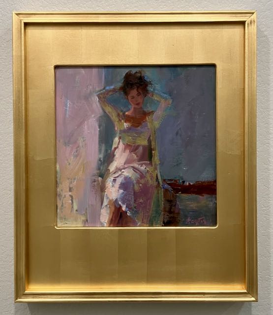
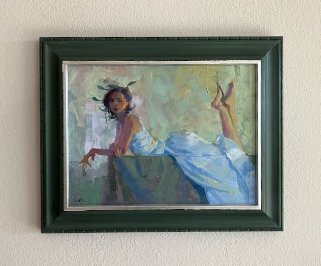
Here’s a better picture of the finished project than the one above in the comparison shot. I concentrated when laying the leaf to keep the lay lines continuous through the cut out area where the painting is. The painting is on panel and was secured with points.
First Light by Diane Eugster A bit of Whimsy and Milk Paint: Frame #280
 Once Upon a Time
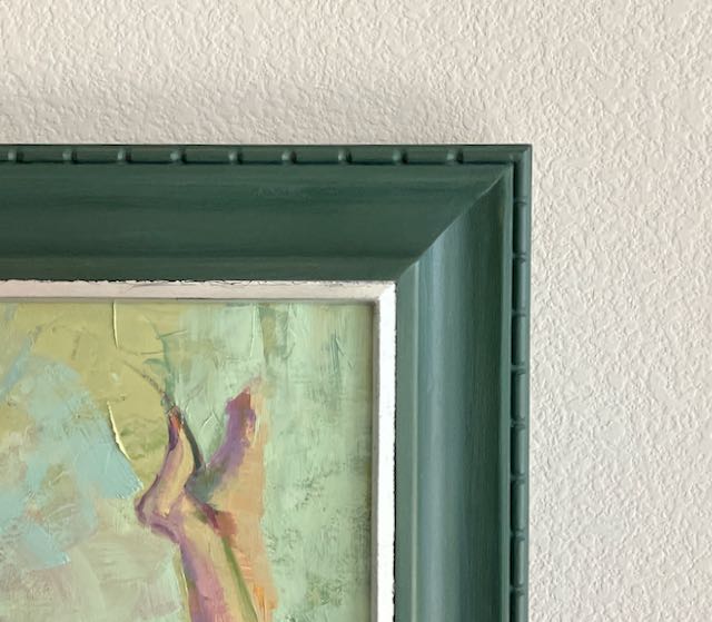 Corner Detail
Here’s the most recent frame from my shop and it was fun to create so thought I’d share the story! It’s oil on canvas measuring 12″x16″ and by my wife, Diane Eugster. When I first saw it in her studio my mind went to a wood nymph; whatever that may be! This painting needed something other than a traditional black/gold frame, something more fun and maybe with a bit of whimsical carving to enhance it.
Creating the Profile
Creating the profile began with my typical Basswood sized approximately 1″ thick by 2 7/8″ wide. The process begins by cutting the backside each pieces at 15° to create a profile that angles the frame away from the wall leaving plenty of room to install a 3/4″ thick canvas. I refer to this as my 15° Profile and it’s a way to angle the frame. I wrote a BLOG about it some time ago. I’ve modified the process somewhat since then but that blog gives you the basic method to do it. It took me less than 2 hours to profile this frame, carving took much longer than that.
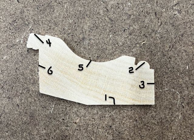
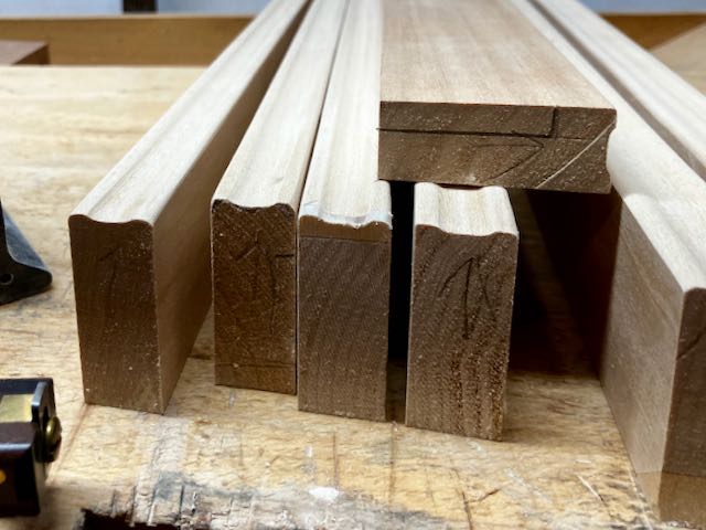
The process began with cutting the 15° angle on the back of the piece, that’s #1 in the picture, this will become the outside edge of the frame. If you do any beading on the frame it’s important to do that before cutting the outside edge 90° to the angled cut. This makes it easier to clamp when gluing the frame together. For this profile I cut a 1/4″ bead on the outside edge, #2 with a small plow plane. Draw a 90° line (#3) from the angled cut to locate the outer edge of the bead. This piece will be cut off after the bead is complete. For this profile I wanted a flat section at the sight edge for gilding, this is #4 and was created with a skewed rabbet plane. To create more interest to the frame I also cut a cove; #5. This was done with a tablesaw, it’s an interesting process and I wrote this BLOG explaining my process. The final cut is #6, the rabbet. This is somewhat tricky so check my blog on how to do it. Very important to note that I always have at least one extra piece of stock about 10-12″ long to set up the tablesaw for all of these cuts.
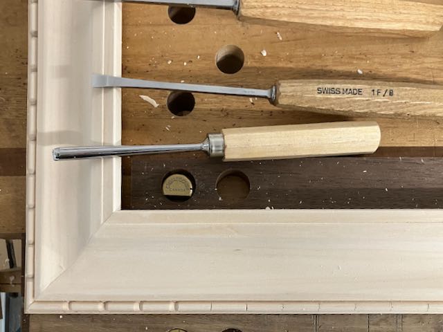
Carving
Not exactly sure what these are called, they look like an elongated bead or a sausage but I’ve seen them called either billets or reels. To figure out the spacing it’s easiest to use a set of dividers and step the divisions off once you decide their approximate length. Do that on a piece of masking tape, not your frame because there’s a lot of trial and error involved and your bead would have all the markings from the divider. Once you’re satisfied with the spacing put the markings on the frame. My preference is to start at the center and work to the ends. Any slight error will show up at the ends only. I used a 1F/8mm skew to divide them, then a 8/6mm gouge to create the rounded ends. Finally a 1S/5mm removes the bits between the reels.
Finishing
I’ve been using milk paint from RMPfinishes (formerly Real Milk Paint) lately to finish some of my frames. I like the effect of it and it comes in a powder form. That means I only mix up a small amount as needed and the powder will keep forever unlike paints that come in a can. For this frame I chose Blue Spruce. I mix 2 ounces of powder with 2 ounces of distilled water and that’s enough to complete the frame. I’ve found that the foam brushes they sell work great, much better than those available from my local big box store. I lightly scuff between coats (2 usually) with a Mirka 1500 pad. This frame has a gilded, silver sight edge so that was taped off and applied with quick set size. Milk paint should be sealed and I’ve used wax, OSMO #3043, and also Platinum Blonde Shellac which I spray on with an air brush. That’s how this frame is sealed, the shellac also seals the imitation silver leaf. The final step is rubbing out the shellac with Liberon wax to take some of the sheen off of the shellac and even out the spray pattern from the air brush.
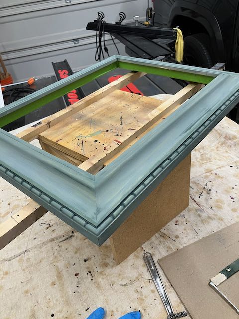 Blue Spruce Milk Paint
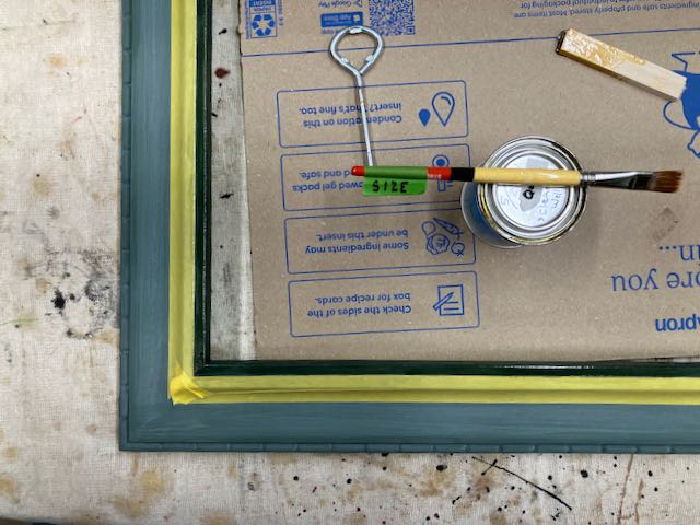 Quick set size for gilding
That’s the process for this profile; in my opinion, adding the cove and the carving creates many shadows and patterns that brings interest to the frame.